Contact us for a quote!
myCNC Controllers and Software
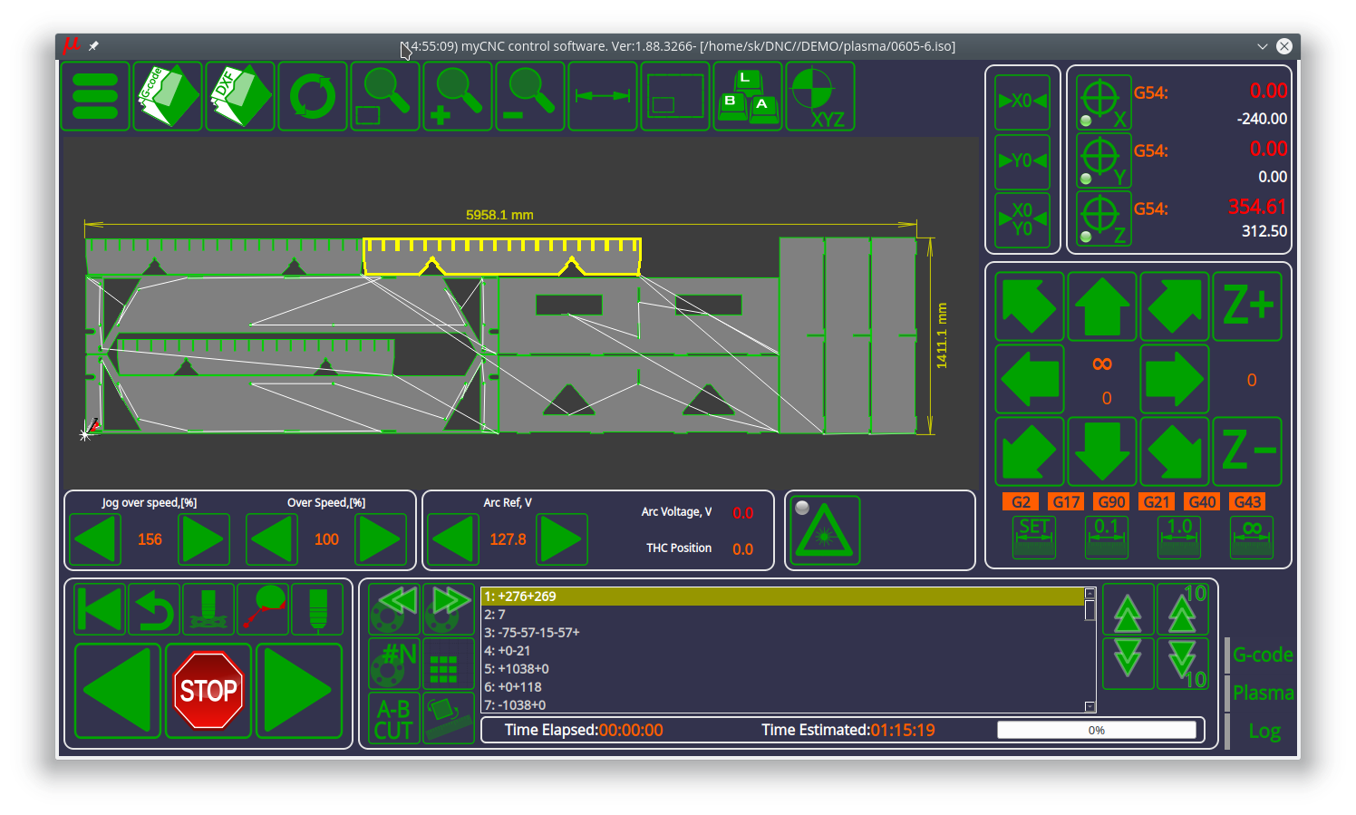
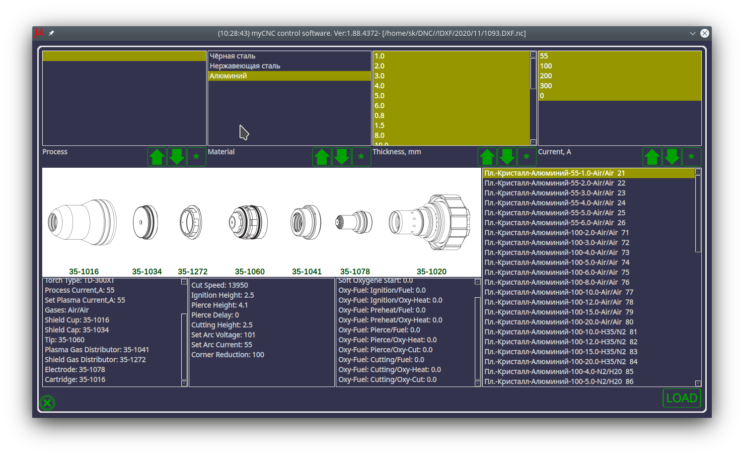
myCNC is a multi-platform CNC Control Software designed for the myCNC line of controllers that can be installed on Windows, Linux, and Embedded Linux Operating systems. Designed and developed by Puruvesi Automation.


Our entry-level offering
ET6
6 motor outputs, 8 inputs and and 7 total outputs. Perfect for smaller projects.
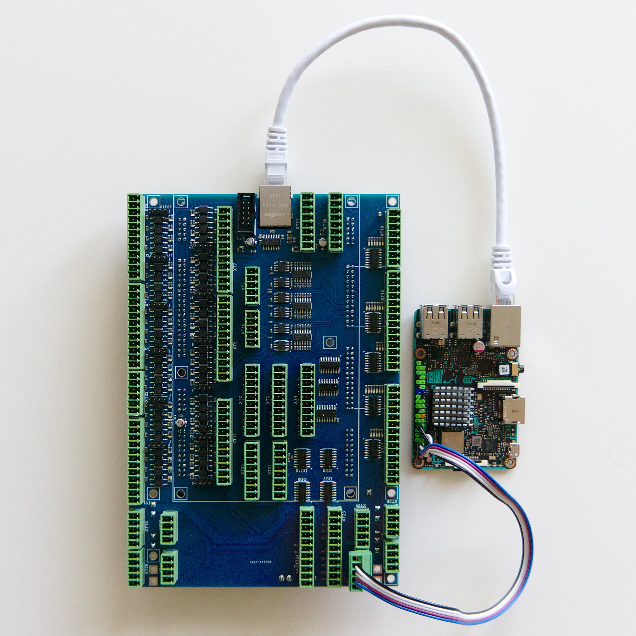
More I/O ports
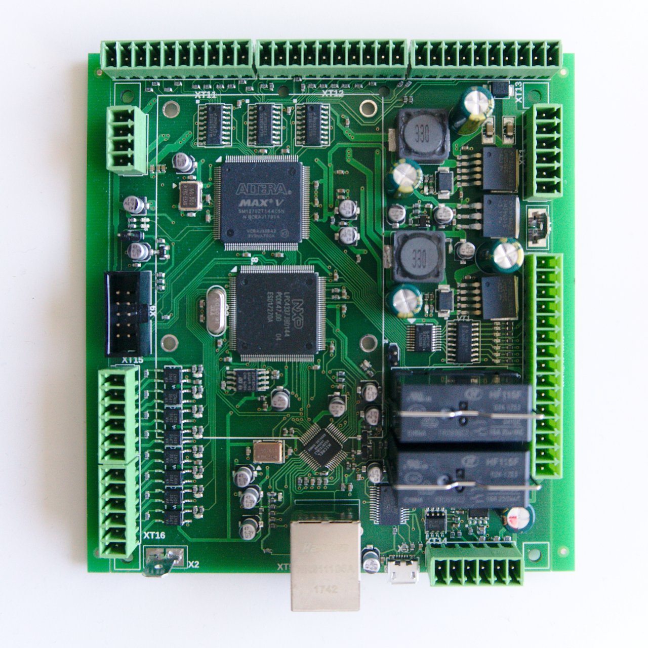
ET10
Based on 204MHz 32bit ARM Cortex-M4 Processor and Altera FPGA logic. 48 inputs, 28 outputs total.
Compare myCNC controllers
Features
ET6
ET7
ET10
ET15
Motor outputs
6
6
6
8
Pulse-Dir
6 channels
6 channels
6 channels
8 channels
Analog -10V/+10V outputs
6 channels
8 channels
Galvanic Isolated inputs
8
16
48
64
Encoder Inputs
3 (AB)
6 channels (4/ABC + 2/AB)
8 channels (ABC)
Closed Loop Motion Control
3 Channels (Pulse/Dir + Encoders)
6 Channels (Pulse/Dir + Encoders), 6 Channels (Analog -10...+10V + Encoders)
8 Channels (Pulse/Dir + Encoders)
Closed Loop PWM control
3 Channels (PWM + ADC)
4 Channels (PWM + ADC)
4 Channels (PWM + ADC)
Built-in THC
Outputs (total)
7
19
28
64
Outputs (Open Collector)
2
11
24
56
PWM Outputs
3
3
4
8
Relay Outputs
2
5
RS485/RS422 Modbus
1
1
2 (#0 reserved)
2
Plasma, oxy-fuel, laser, tangential cutting, and more.
Special-purpose G/M codes, Torch Height Control (THC) and ATC. Large G-code files of up to 1GB. Fully customizable GUI, an advanced 2D/3D visualization, and real-time IO monitoring.
The myCNC software is free to download and works with every myCNC controller.
Countries
Years in service